저번 포스팅에서는 Pre-configured Example 을 가져오는 방법을 알아보았다. 이번에는 이것을 변형하는 과정을 보도록 한다.
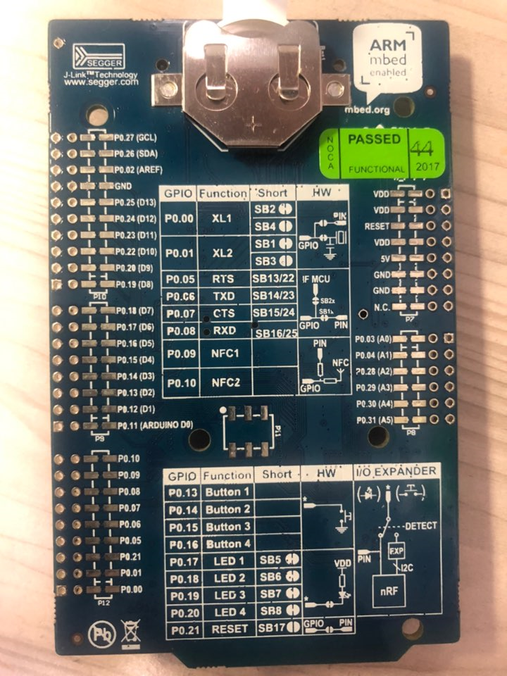
우선, 보드 뒤쪽에 보면 I/O Pin 번호가 적혀있는데 13 - 16은 보드 내부에 위치한 버튼, 17- 20은 LED임을 알 수 있다.
0. Internal LED 사용
GPIO를 Output으로 쓸 때의 Header / Function
| #include "nrf_gpio.h" | GPIO 헤더 추가 |
| nrf_ nrf_gpio_cfg_output(uint32_t pin_number); | 핀을 output 으로 설정 |
| nrf_gpio_range_cfg_output (uint32_t start_pin_number,uint32_t end_pin_number); | 여러 핀을 같은 configuration output 으로 설정 |
| nrf_gpio_pin_set(uint32_t pin_number); | Pin 출력 1 로 설정(Set) |
| nrf_gpio_pin_reset(uint32_t pin_number); | Pin 출력 0으로 설정 (Reset) |
| nrf_gpio_pin_toggle(uint32_t pin_number); | Pin 출력 Toggle (Delay 함수 써야 눈으로 변화가 보임) |
핀을 설정할 때의 Internal Parameter를 일일이 설정하려면 다음 함수를 이용한다.
STATIC_INLINE void nrf_gpio_cfg (
uint32_t pin_number,
nrf_gpio_pin_dir_t dir,
nrf_gpio_pin_input_t,
nrf_gpio_pin_pull_t pull,
nrf_gpio_pin_drive_t drive,
nrf_gpio_pin_sense_t sense
)
main 함수는 다음과 같이 바꿀 수 있다.
#include <stdbool.h>
#include <stdint.h>
#include "nrf_delay.h"
#include "boards.h"
#include "nrf_gpio.h"

#define led 17
#define led2 19


/**
 * @brief Function for application main entry.
 */
int main(void)
{
  nrf_gpio_cfg_output(led); // configures the pin as output
  nrf_gpio_cfg_output(led2);

  while(1)
  {
    nrf_gpio_pin_set(led);  // setting logic 1 on pin 17
    nrf_delay_ms(100);
    nrf_gpio_pin_clear(led);  // Setting logic 0 on pin 17
    nrf_delay_ms(100);

    nrf_gpio_pin_toggle(led2);

  }


}
On-board LED에 대해 간략히 설명하자면, LED의 cathod terminal이 nRF 보드에 연결되어 있고 anode는 +3.3[V] 전원에 연결되어 있다. 따라서 Pin을 1로 설정하면 3.3[V]가 흐르게 되어 LED를 중간에 두고 potential difference가 생기지 않으므로 불이 들어오지 않지만, Pin을 0으로 설정하면 3.3[V]의 전위차가 생겨 LED에 불이 들어오게 된다. 따라서 익숙하지 않을 수 있지만 nrf_pin_clear(LED)가 LED에 불이 들어오게 하는 함수라고 보면 된다.
1. Internal Button 사용
pull configuration은 풀업저항을 사용할 것인지, 풀다운 저항을 사용할 것인지를 나타낸다. 세 가지 Constant가 제공된다.
NRF_GPIO_PIN_PULLUP
NRF_GPIO_PIN_PULLDOWN
NRF_GPIO_PIN_NOPULL
GPIO Input으로 쓸 때의 Function
| nrf_gpio_cfg_input( uint32_t pin_number, nrf_gpio_pin_pull_t pull_config); |
pin 의 configuration을 input으로 설정 |
| nrf_gpio_range_cfg_input ( uint32_t pin_range_start, uint32_t pin_range_end, nrf_gpio_pin_pull_t pull_config ) |
multiple consecutive pin의 configuration을 input으로 사용 |
| nrf_gpio_pin_read(uint32_t pin_number); | pin 의 input을 읽음 |
| nrf_gpio_port_in_read(); | 0 번 핀부터 31번 핀의 status를 모두 읽어들임 |
다음은 1번 버튼을 누르면 LED가 켜지고, 누르지 않으면 LED가 꺼지는 예제이다.
#include "nrf_gpio.h"

#define LED 17
#define BUTTON 13


/**
 * @brief Function for application main entry.
 */
int main(void)
{
  nrf_gpio_cfg_output(LED); // configures the pin as output
  nrf_gpio_cfg_input(BUTTON, NRF_GPIO_PIN_PULLUP); // configures the button pin as input pin
  nrf_gpio_pin_set(LED); // turn off the led

  while(true)
  {
    if(nrf_gpio_pin_read(BUTTON) == 0)
    {
      nrf_gpio_pin_clear(LED); // turn on led
      while(nrf_gpio_pin_read(BUTTON) == 0); // start in this loop until the button is released

      nrf_gpio_pin_set(LED); // turns off the led
    }

  }

}
'EE > Embedded Systems' 카테고리의 다른 글
| [nRF52BLE][2]Connection and Softdevice (0) | 2021.01.04 |
|---|---|
| [nRF52BLE][1]Bluetooth Communication Scheme (0) | 2021.01.04 |
| Nordic nRF52 UART 통신 (0) | 2020.12.23 |
| Segger Embedded Studio - IDE Tips (0) | 2020.12.23 |
| Nordic Semiconductor - nRF MCU and Bluetooth Low Energy (1) | 2020.12.22 |